Two proposals for a robotic welding cell with the same robot can have very different scopes. The difference is rarely in the arm. It is in the positioner, the fixture, the power source, the safeguards and in who is responsible for start-up. Anyone comparing by the robot is comparing the line that decides the result the least.
This article describes each component, the most common layouts and the list of what must be defined before asking for a quote. The earlier decision, whether to automate the process at all, is in the robotic welding guide.
Welding robot and cell: what is the difference
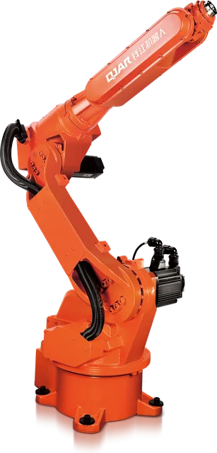
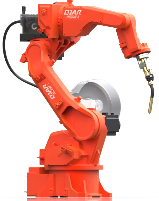
The welding robot is the 6-axis arm with its controller. The robotic welding cell is the complete system that receives tacked parts and delivers welded parts, with a known cycle and documented safety. For ISO 10218, it is this application, not the robot alone, that has to be designed and validated.
The components, one by one
| Component | Role in the cell | What to check in the proposal |
|---|---|---|
| Welding robot | Carries the torch along the programmed path | Reach over the part already mounted on the fixture, repeatability |
| Controller and cabinet | Controls the robot and the external axes, with emergency stop and main switch | How many external axes it controls in coordinated motion |
| Welding power source and wire feeder | Delivers the arc with stable parameters | Communication integrated with the robot controller, process and duty cycle |
| Torch and cleaning station | Carries wire, gas and current; the station cleans the nozzle | Cooling compatible with the current and the cycle |
| Fixture | Ensures the joint is always in the same place | Who designs it, who builds it and how the part is loaded |
| Positioner | Rotates and tilts the part for access and welding position | Number of axes, load, synchronization with the robot |
| Track | Moves the robot along long parts | Load class and repeatability |
| Guards and interlocks | Prevent access to the hazard zone while the robot moves | Safety scope and documentation in Portuguese |
| Fume extraction | Captures fumes at the weld point | Whether it is in scope or left to the customer |
| Operator interface | Program selection, start, diagnostics | Production and alarm records |
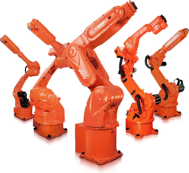
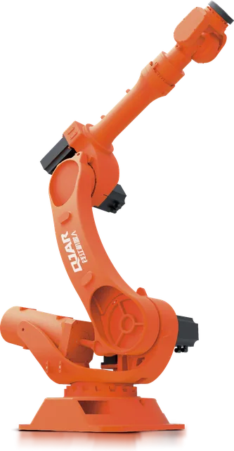
In the QJAR line, robot, control cabinet, digital welding power source, positioners and track come from the same manufacturer, and the welding power source has communication integrated with the robot controller.
Which welding robot
For arc welding the tool is light. What decides is reach and repeatability.
| Model | Payload (kg) | Reach (mm) | Repeatability (mm) | Mass (kg) |
|---|---|---|---|---|
| QJRH4-1A | 4 | 1,410.5 | ±0.03 | 150 |
| QJR6-1400H | 6 | 1,456 | ±0.08 | 150 |
| QJR6-2000H | 6 | 2,014 | ±0.08 | 230 |
The difference between about 1.4 m and 2 m of reach is not a detail. With more reach the robot covers wider parts or two stations without a track. With less reach the cell is compact and the arm works in more favourable postures over small parts. The answer comes from the envelope of the part already mounted on the fixture and the positioner. The general criteria for reading the datasheet are in the industrial robot guide.
Fixture: where quality starts
The robot always takes the torch to the same point. It is up to the fixture to guarantee that the joint is at that point. It has to locate the part on stable references, withstand heat distortion without trapping the part after welding and leave a clear path for the torch.
Three questions help to assess the proposal: who designs the fixture, how the operator loads and checks the part, and how long the changeover to another product takes. In part families, a fixture with interchangeable elements shortens that changeover.
Positioners
The positioner exists for two reasons: to bring each joint to the most favourable welding position, preferably flat (PA in ISO 6947), and to give the torch access without anyone having to turn the part.
| Type | How it works | Typical part |
|---|---|---|
| 1 axis | Headstock and tailstock with servomotor | Long parts that rotate about their own length |
| 2 axes | Rotation and tilt | Volumetric parts welded in the flat position |
| L type | Two axes on an L arm, with free access around the part | Parts with welds on many faces |
| 3 axes | Station exchange: the operator loads one side while the robot welds the other | Continuous production with manual loading |
What makes the positioner part of the process is coordinated motion. Robot and positioner move together, so that the torch keeps constant speed and angle relative to the joint while the part rotates.
Linear track
When the part is longer than the robot's reach, the arm travels on a track, which works as an additional axis. The track in the line uses a helical rack, servomotor and linear guides, in three classes:
| Class | Total load (kg) | Wrist payload (kg) | Repeatability (mm) |
|---|---|---|---|
| Light | up to 1,000 | up to 50 | ±0.08 |
| Medium | up to 3,000 | up to 300 | ±0.10 |
| Heavy | up to 10,000 | up to 1,000 | ±0.15 |
In welding, the repeatability of the track enters the calculation together with that of the robot. That is why the track class is chosen by the part and the process, not only by the weight of the arm.
Most common layouts
| Layout | When it applies | Point of attention |
|---|---|---|
| One station with fixed table | Small parts, welded without repositioning | The robot waits during part exchange |
| Two stations | Continuous volume with manual loading | Separation between the welding station and the loading station |
| Headstock and tailstock | Beams, shafts, frames and other long parts | Fixture stiffness along the length |
| 2 axes or L type | Parts with welds on several faces | Load and centre of gravity of part plus fixture |
| Robot on track | Parts longer than the robot's reach | Track class and cabling |
Layouts combine. A cell for long parts can have a track plus headstock and tailstock. A high-volume cell can have two stations, each with a positioner.
Safety and environment
A welding cell adds the hazards of the arc to those of a moving robot: radiation, spatter and fumes. In practice this means an enclosure that contains arc radiation, a loading access protected by an interlocked door or by a presence-sensing device, a reset with a full view of the area, and extraction at the weld point.
The reference in Brazil is NR-12, which recognizes ISO 10218 for robot systems. What the regulation requires, item by item, is in NR-12 for robot cells. It is worth checking whether the safety scope and the documentation in Portuguese are inside the proposal or outside it.
What to define before asking for a quote
A comparable proposal comes from a complete request:
- Drawings or 3D models of the parts, with the joints indicated.
- Material, thicknesses and the welding process in use.
- Total bead length per part.
- Annual volume, batch size and number of shifts.
- Target cycle time per part.
- Tolerances of the parts arriving at welding.
- Bead acceptance criteria and applicable standard.
- Available floor area and ceiling height.
- Utilities on site: three-phase voltage, compressed air, gases and extraction.
- Who supplies the fixtures and who operates the cell.
With this data the discussion stops being about the robot and becomes about the result: parts per shift, quality and start-up date. The impact of each block on the investment is in industrial robot cost, and the criteria for assessing who will execute the project are in the article on the robot integrator.
Four mistakes are frequent at this stage:
- choosing the robot before defining positioner and fixture;
- asking for a quote without stating the tolerance of the parts arriving at welding;
- treating extraction and safety as items to be solved later;
- sizing for a single part and forgetting the family that comes next.
Frequently asked questions
What is a robotic welding cell made of?
A welding robot with its controller, a welding power source with wire feeder, a torch with cleaning station, a fixture, a positioner or table, interlocked safeguards, fume extraction and an operator interface. Depending on the part, a track and a second loading station are added.
What is the difference between a welding robot and a robotic welding cell?
The welding robot is the arm with its controller. The cell is the system that produces: robot, power source, torch, positioner, fixture, safety and operation. Proposals that look equivalent by the robot usually differ precisely in the other items.
When does the cell need a positioner?
When the part has welds on several faces or when quality calls for welding in the flat position. The positioner rotates and tilts the part to bring each joint to the best position and to give the torch access without manual repositioning.
Can the same cell weld different parts?
Yes. Each part has its own fixture and program, and the changeover is planned in the project. Families of similar parts use the same positioner and part of the fixtures, which shortens changeover time.
Does a robotic welding cell in Brazil have to comply with NR-12?
Yes. NR-12 applies to the cell as a machine, and item 12.1.12 recognizes as compliant the robot systems that follow ISO 10218-1, ISO 10218-2 and ISO/TS 15066. The regulation requires guards, interlocks, emergency stop and a manual in Portuguese; training, which it assigns to the employer, is worth agreeing in the project scope.
Talk to BR Robotics
BR Robotics designs and integrates welding cells with QJAR robots in Brazil. Send the part, the volume and the target cycle time: the reply comes with the recommended model, the cell layout and the quote. Talk to BR Robotics or see robots, positioners and track.
Sources
- EVST Brasil, datasheets of robots, positioners and track
- ISO 10218-2:2025, Robotics: Safety requirements, Part 2: Industrial robot applications and robot cells
- ISO 6947:2019, Welding and allied processes: Welding positions
- NR-12, Safety at Work in Machinery and Equipment (Brazilian Ministry of Labour and Employment, in Portuguese)